Set the jumpers like this: (10-5 = DS0, 10-15 = DS1)
Note, you can switch the colour of the activity LED with the jumper that is between 1-6-11. (1-6 = amber, 6-11 = green).
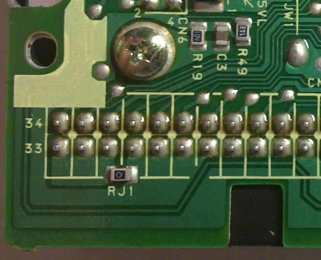
Find the test pad that is on the trace that goes to pin 34 of the data connector.
There is a wide yellow silkscreen blob on top of the trace that makes following the trace a little difficult, but you can easily confirm it with your multimeter.
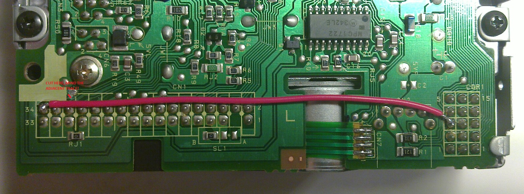
Cut the trace before or after the test pad. Be careful, there is another trace right next to the one you want to cut.
Solder a wire from pin 3 of the jumper block to pin 34 of the data connector.
Unmodified:
Modified:
Here are the descriptions for the jumper pins:
Note, the numbers inside the circles explain which data connector pin that particular jumper pin is connected to.